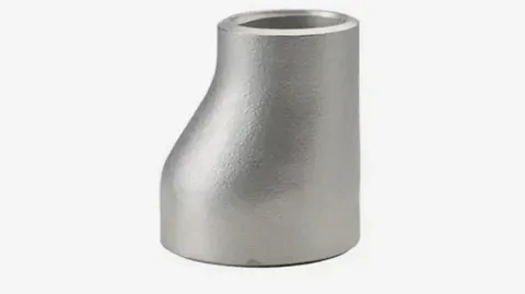
Eccentric Reducer - Butt-Weld Pipe Fitting
Our eccentric butt-weld reducer changes pipe size while keeping one side of the bore level with the adjacent pipe. On horizontal lines a flat-top orientation prevents trapped air from accumulating, while a flat-bottom orientation ensures complete gravity drainage. This makes the eccentric reducer the recommended standard on horizontal runs in accordance with good piping practice.
Each reducer is supplied with factory-machined weld-end bevels to ASME B16.25 for full-penetration butt welding. Full heat-number traceability and EN 10204 3.1 material test certificates are available to satisfy UK site quality requirements.
Standards & Materials
Manufactured to BS EN 10253-2 and ASME B16.9 in a choice of carbon and stainless steel grades to suit your operating conditions.
| Attribute | Specification |
|---|---|
| Manufacturing Standard | BS EN 10253-2 / ASME B16.9 |
| Carbon Steel | ASTM A234 WPB |
| Stainless Steel | ASTM A403 WP304 / WP304L / WP316 / WP316L |
| Special Grades | Duplex & Super Duplex (UNS S31803 / S32205 / S32750), Alloy 20, Inconel 625 / 825, Monel 400, Hastelloy C-276 - available on request |
| Fabrication | Seamless or welded |
| Weld-End Bevel | ASME B16.25, 37.5° half-angle |
| Test Pressure | Up to 1 500 psi (103 bar) |
Dimensions & Sizes
Available in a wide range of reduction combinations up to 24" in schedules 10, 40 and 80. The table below shows representative ASME B16.9 overall length H and offset E for common eccentric reducer size combinations.
| Large End NPS | Small End NPS | Overall Length H (mm) | Offset E (mm) |
|---|---|---|---|
| 3/4" | 1/2" | 38 | 10 |
| 1" | 1/2" | 38 | 15 |
| 1" | 3/4" | 38 | 8 |
| 1-1/2" | 3/4" | 64 | 32 |
| 1-1/2" | 1" | 64 | 24 |
| 2" | 1" | 76 | 32 |
| 3" | 2" | 89 | 32 |
| 4" | 3" | 102 | 32 |
| 6" | 4" | 140 | 38 |
| 8" | 6" | 178 | 38 |
| 10" | 8" | 229 | 51 |
| 12" | 10" | 330 | 51 |
Performance & Benefits
The offset bore keeps the flow path level on one side, preventing air pockets from forming on horizontal runs (flat-top orientation) and allowing full gravity drainage (flat-bottom orientation). This design is essential for pump suction lines, condensate drip legs and any horizontal service where trapped air or liquid could cause corrosion, water hammer or reduced thermal efficiency.
Typical Applications
Used across water treatment works, chemical dosing systems, steam and condensate networks, heat exchanger installations and pumping stations throughout the UK where horizontal pipework must self-drain or remain free of air pockets.
Quality Assurance & Traceability
Every fitting is manufactured to BS EN 10253-2 and ASME B16.9 and supplied with full material traceability and EN 10204 Type 3.1 test certificates. Heat numbers are recorded throughout production to support inspection, QA and UK project-compliance requirements.
Supply & Delivery
Stocked at our Sheffield, UK facility and delivered nationwide across England, Scotland and Wales. We offer fast dispatch from stock with tracked UK delivery to site, and next-day options for common sizes.
-
Which sizes and schedules are available?
Available from 1/2" (DN15) to 24" (DN600) in schedule 10, 40 and 80, in both metric and imperial sizes to suit UK installations.
-
Should I orient the eccentric reducer flat-top or flat-bottom?
On horizontal pump suction lines, orient the reducer with the flat side on top (flat-top) to prevent air from being trapped at the high point of the reducer. On horizontal lines that must drain by gravity, orient the flat side on the bottom (flat-bottom) so condensate and sediment flow freely. Always confirm orientation with your piping designer or the pump manufacturer's requirements.
-
Can you provide material certificates?
Yes. Material test certificates and full traceability documentation are available with every order, to project and quality-management requirements.
-
Do you deliver across the UK?
We deliver nationwide throughout England, Scotland and Wales, with fast dispatch from stock and tracked deliveries to site.